3D Design for Printing
This section builds on Introduction to 3D Printing and explores how to create effective models, understand key file formats, and utilize tools like Tinkercad to bring your designs to life.
Introduction to 3D Modeling
What is a 3D Model?
A 3D model is a digital representation of a physical object, defined by its geometry, shape, and structure. These models are created using Computer-Aided Design (CAD) software and are essential for 3D printing, as they provide the blueprint that printers follow to build objects layer by layer.
Common 3D File Formats
Understanding different file formats is crucial for 3D printing:
STL (Stereolithography): The most widely used format, representing models as a mesh of triangles. It doesn’t support color or material information.
OBJ (Object File): Supports color and texture information, making it suitable for more detailed models.
STEP (Standard for the Exchange of Product Model Data): Used for sharing models between different CAD programs, preserving complex geometry and assembly information.
3MF (3D Manufacturing Format): A modern format that includes color, material, and other metadata, aiming to be a comprehensive solution for 3D printing needs. Be aware that slicer software can produce two kinds of .3mf files: a project save (via
File > Save) that contains only models and settings, and a sliced export (via “Export plate sliced file”) that also embeds print time, filament usage, and G-code data. For Jotform submission, you must use the sliced export — see Exporting a Sliced .3mf for Jotform Submission.
Design Thinking for Printing
Thinking in Layers
3D printers build objects layer by layer. This additive process means that each new layer must be supported by the one below it. Designing with this in mind ensures structural integrity and printability.
Orientation / Overhangs
There is nothing wrong with using supports in your designs. Sometimes there is no workaround or design choice that can avoid them, and supports will be absolutely necessary. That said, supports do have downsides:
Wasted filament
Wasted time and effort needed to remove supports
Longer print times
Supported sections generally have lower surface quality.
Supported sections are more likely to fail than non-supported sections.
This does not mean you should avoid supports at all costs, but rather that you should be aware of the downsides and design to avoid them when possible.
‘Bad’ Overhangs and the Power of 45
An overhang is a section of a print that extends outward without any support beneath it. This often causes the filament to droop, leading to not only a visual quality issue but also a functional one.
Often, future layers depend on the overhangs, but if the overhangs droop, the future layers may not have anything to attach to. This often leads to print failures. The best rule of thumb is to keep any angles (that would cause an overhang) at 45 degrees.
Here’s an example model that shows what the slicer considers a ‘bad’ overhang:
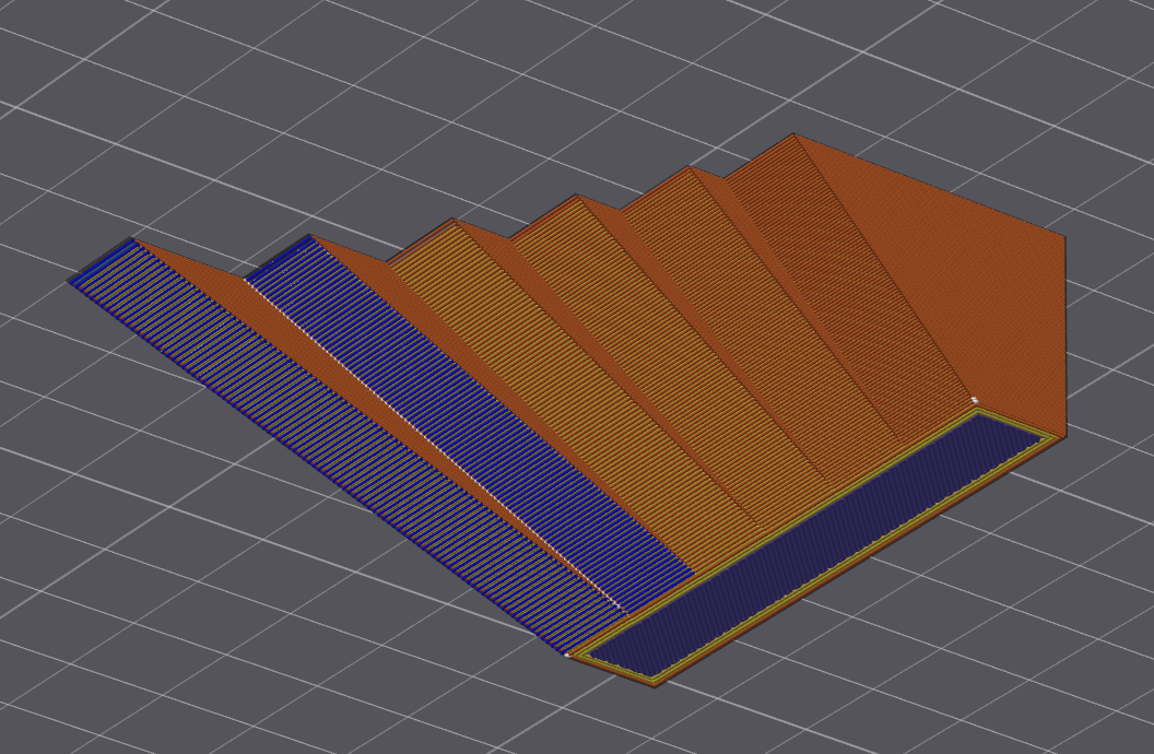
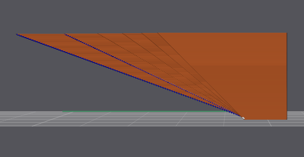
In the images above, you can see orange and blue parts of a sliced model. Orange sections indicate normal Outer Walls that will print in good quality, while blue sections indicate Overhang Walls that are highly likely to droop and have quality issues.
The leftmost side of the model starts with a 45-degree angle, with each section decreasing the angle. It goes: 45, 35, 25, 15, then 10 degrees.
Although the slicer can consider the 35 and 25 degrees “acceptable”, these are in ideal conditions and are not guaranteed to print well. External factors like cooling, filament type, and printer settings can all affect the print quality. In your designs, stick with 45 degrees for the best results and go lower only if you have to.
There is a quick workaround for getting really low-angle overhangs to print better: you can decrease the layer height from the default 0.20 mm to something lower like 0.08 mm per layer.
The same model with 0.08 mm layer height now looks like this when sliced:
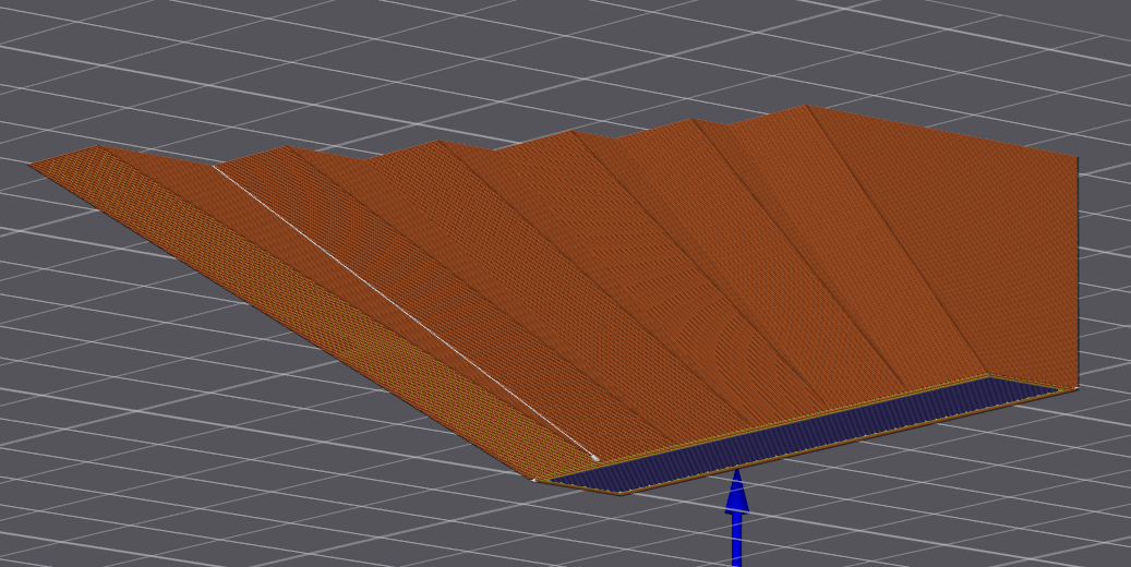
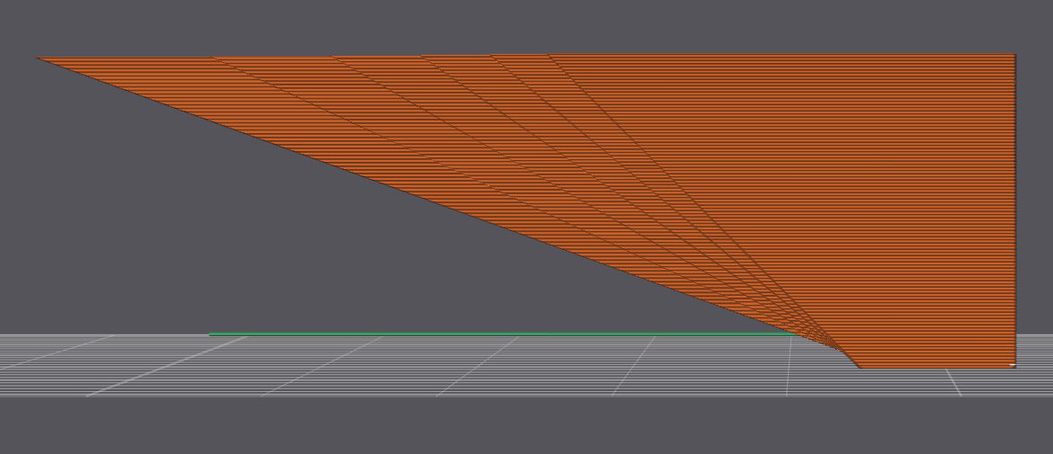
Keep in mind, though, that everything has a tradeoff. Lowering the layer height will increase print time and filament usage, so use this workaround sparingly. This “workaround” is not a replacement for good design practices, nor is it a solution to bad design practices.
Bridges are the Best
FDM printers generally cannot print on thin air, but they are able to create bridges over gaps when there is something to support the filament on both sides. At short lengths, at or under 20mm, bridges are very reliable and visually print well. If you need to print over air, without supports, make sure it’s a bridge.
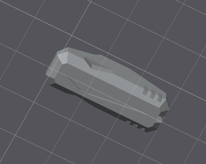
Here are some examples of bridges being used to add details to models; the light blue sections are the bridges.
Unsliced:
Sliced:
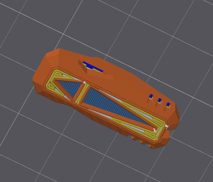
The yellow section is the part of the model touching the build plate. You can see the light blue section is not touching the build plate, and even the darker blue sections that are deemed ‘bad’ overhangs print okay because they are so small that they act like bridges.
Choose the Bottom of Your Model Right Away
When starting to design a model, choose the face of the model that will be attached to the build plate. Knowing the orientation of your print from the start can help you more easily identify where you have ‘bad’ overhangs. This is helpful because it’s easier to catch and fix ‘bad’ overhangs right away instead of when your model is nearing completion.
Bed Adhesion
Brims are always useful for creating more bed adhesion for thin or small parts, but it is good practice to avoid them when possible (covered more later on). Creating good bed adhesion mostly means designing the bottoms of your prints to have a good-sized connection to the build plate and avoiding long, thin sections.
Here are some examples of good-sized bottom sections for bed adhesion:
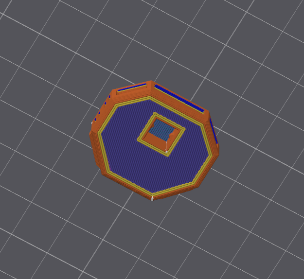
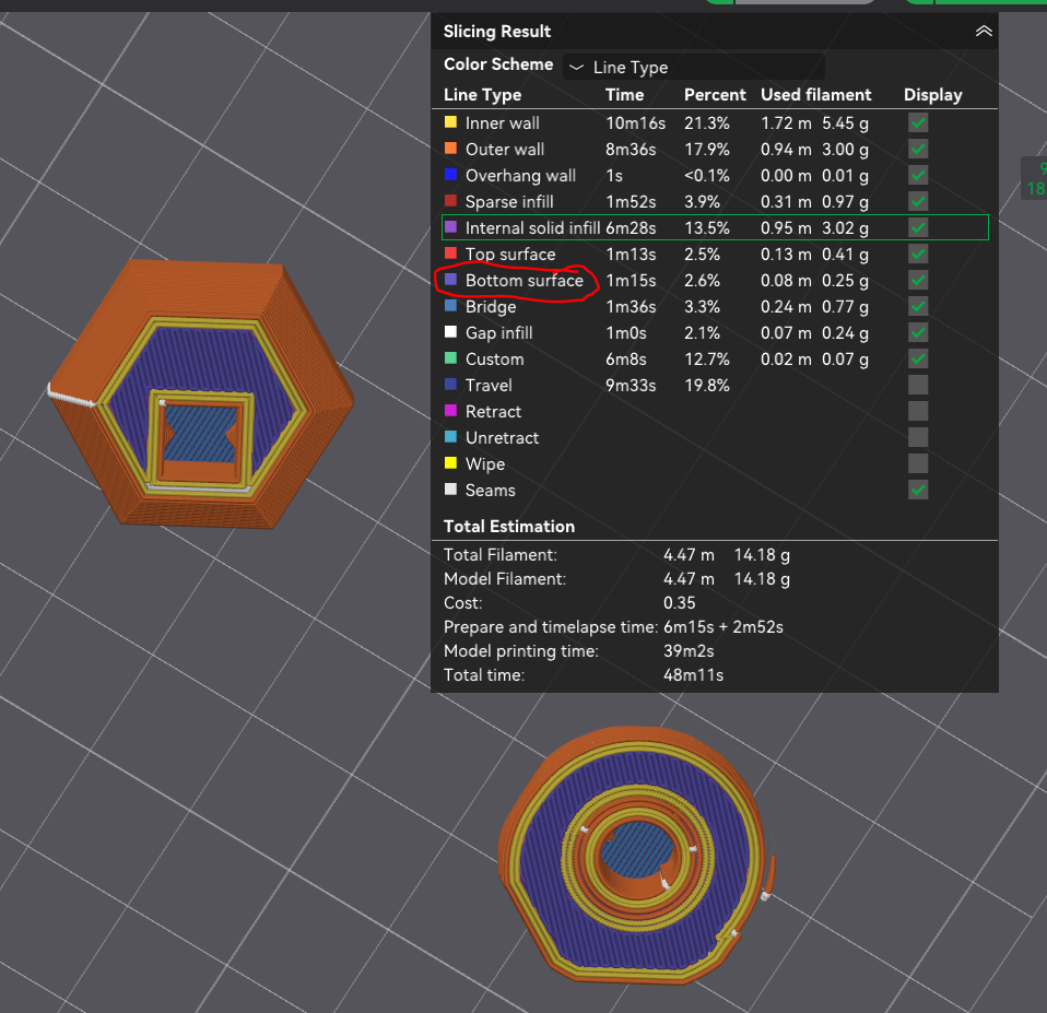
Thus, if you are not seeing any bottom surface sections, it is not a good sign.
Here is an example where the bed adhesion is borderline unreliable:
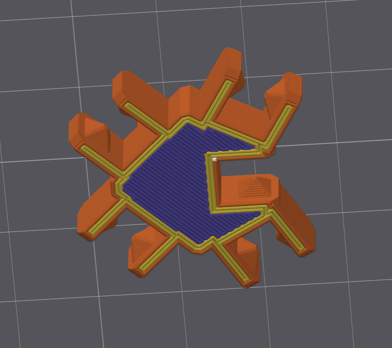
You can see that there are thin walls of yellow that jut out from the base. In these thin walls, we can see orange Outer Walls, yellow Inner Walls, but no blue-purple Bottom Surface. Any thinner than this will significantly increase the probability of print failures due to bad bed adhesion.
For reference, the thin walls in the image above are 2mm thick. Here’s a comparison with a 2mm thick wall and a 1mm thick wall:
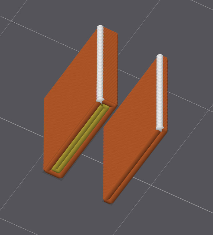
You can see the 1mm thick wall has only orange Outer Walls and no yellow Inner Walls. This would definitely be too thin and should be avoided.
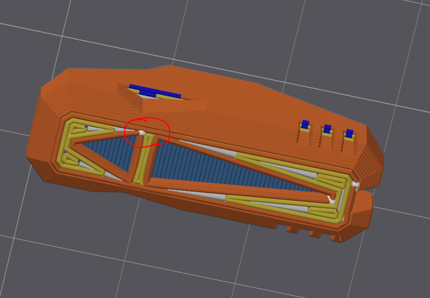
Generally, you would consider this circled area too small and thin for good bed adhesion; however, since it’s surrounded on both sides by larger areas, it does well.
Dimensional Accuracy and Fitment / Tolerance
Did you know that if you print a 10 mm cube and plan to put it inside a 10 mm square hole, it will not fit? Either the hole will be too small or the cube will be too big – maybe even both!
As plastics cool, they shrink. So, if you print a 10 mm cube, it may actually be 9.8 mm or 10.2 mm. This is called shrinkage and is a common issue in 3D printing. The amount of shrinkage depends on many factors, including the type of plastic, the temperature of the build plate, and the ambient temperature. Shrinkage can also depend on the size of the model; larger models tend to shrink more than smaller ones.
Luckily, there are ways to account for this shrinkage in your designs. The most common way is to add clearance between the two parts that need to fit together. This clearance is the amount of space between the two parts and is usually measured in millimeters, also known as tolerance. The amount of clearance needed depends on the type of fitment, or the type of fit you want between the two parts.
For example, consider the following image:
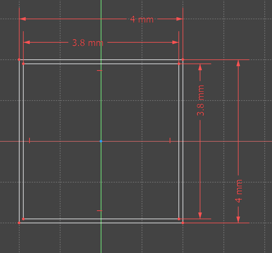
In the image above, you can see a 0.1mm clearance, where the inner square has 0.1mm of space around it on all sides.
If the clearance between two parts is too small, the parts will be too tight to fit together (or won’t fit together at all). Conversely, if the clearance is too large, the parts will be too loose and may not stay together. Finding the right balance is key to ensuring a successful fit.
As a rule of thumb for your designs, fitment can be classified into three categories: Press Fit, Slip Fit, and Clearance Fit.
Fitment Type |
Description |
Clearance Needed |
|---|---|---|
Press Fit |
Parts are designed to fit tightly together, requiring force to assemble. Ideal for permanent joints. |
|
Slip Fit |
Parts can slide together easily but may not stay together without additional support. Useful for temporary assemblies, e.g., snap joints or assemblies that may need to be disassembled. |
|
Clearance (Loose) Fit |
Parts have a gap between them, allowing for easy movement or assembly. Suitable for loose joints. |
|
Let’s say you are designing a dowel rod (a long cylindrical rod) that needs to fit into a hole. You need the dowel rod to be 10mm in diameter and tightly fit into a hole that is also 10mm in diameter. You know that if you printed the dowel rod and the hole at 10mm, they would not fit together. So, you need to add some clearance to your model. You can either:
Increase the diameter of the hole to
10.2mm, so the10mmdowel rod fits inside it.Decrease the diameter of the dowel rod to
9.8mm, so it fits inside the10mmhole.
What you choose to do depends on the design of your model. Generally speaking, it is recommended to increase the size of the hole rather than decrease the size of the dowel rod. This is because it is easier to make a hole larger than it is to make a rod smaller. Additionally, if you make the dowel rod smaller, it may not be strong enough to hold up under stress.
Z-Height and Z-Accuracy
Let’s say you are planning to print a model that is exactly 0.50mm tall. You design your model, slice it, and send it off to be printed. Afterward, you use calipers to measure the height of the model and find that it is actually 0.4mm tall. Wait, what happened? You designed and sliced your model to be 0.5mm tall, so why did it not print at that height?
When the height of the model cannot be evenly divided by the layer height, the slicer uses a rounding algorithm to determine the number of layers required. The slicer processes the 3D model layer by layer. When it reaches the top layer, it decides whether to round up or down based on the center Z height of the topmost line compared to the actual height of the model.
Condition for Top Layer |
Top Layer Exists? |
|---|---|
Model Height > Center Z Height of Topmost Line |
Yes! The topmost layer of the model exists. |
Model Height <= Center Z Height of Topmost Line |
No! The previous layer is taken as the topmost layer of the model. |
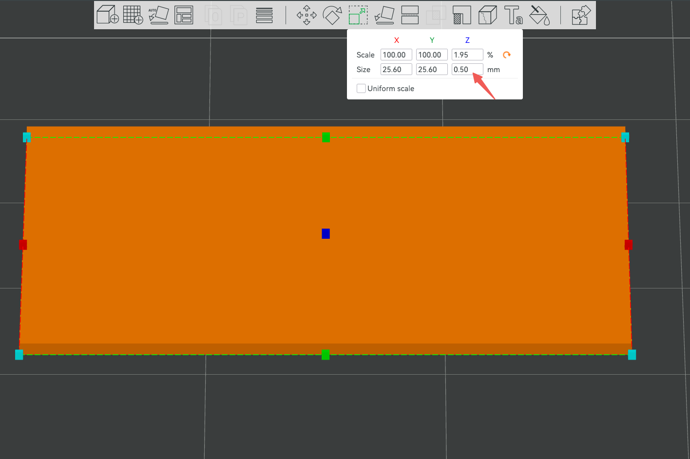
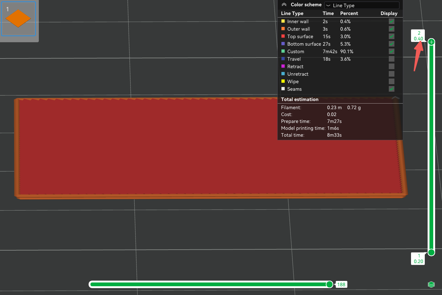
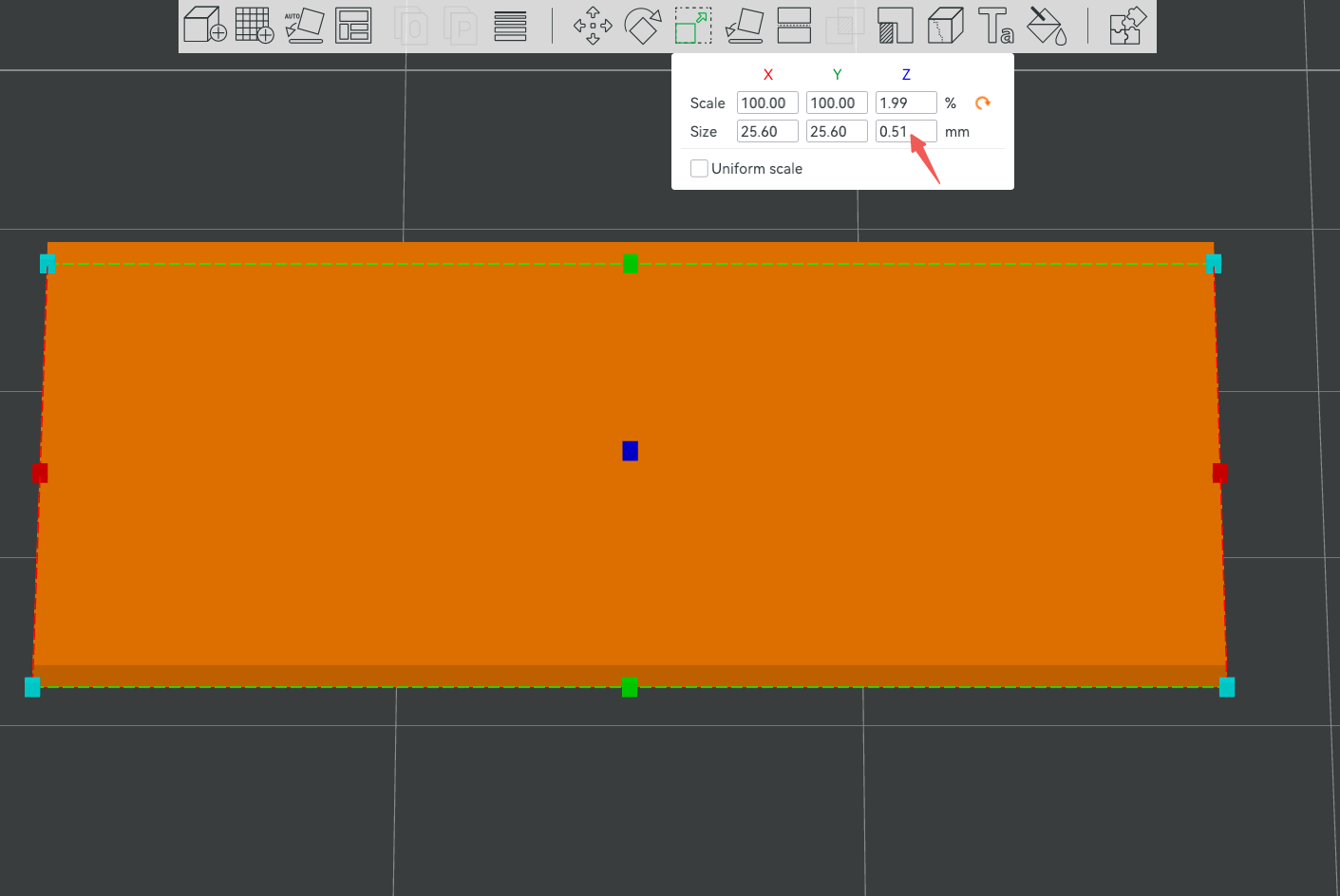
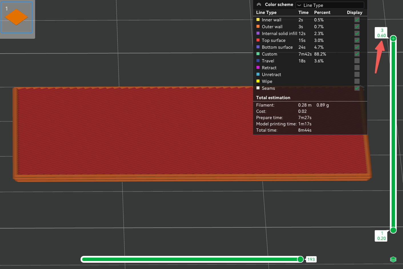
To visualize this, view the results with a layer height of 0.2mm and model heights of 0.5mm and 0.51mm, respectively.
When the height of the model is 0.5mm, the height of the first two layers is 0.4mm, and the height of the center Z of the third layer is 0.5mm (0.2+0.2+0.1) = the model height 0.5mm, so the third layer does not exist, and there are only 2 layers after slicing.
When the model height is 0.51mm, the center Z height of the third layer is 0.5mm < the model height 0.51mm, so the third layer exists and there will be three layers after slicing.
This is called Z-accuracy and can be a frustrating issue in 3D printing that affects the fitment of your model. If your model is not the correct height and other parts depend on its accuracy, your assembly may not fit together or work as intended.
When designing your models, you may need to keep in mind their Z-height. The Z-height is the height of your model along the Z-axis (the vertical axis). So, what do you do about this? We are talking about a difference of 0.1mm here – should you even care? Well, yes and no.
The difference of 0.1mm may not seem like a lot, but if the model’s Z-accuracy matters, that small difference can be significant. So what do you do? You can either:
Design your parts to be divisible by the layer height. For example, if your layer height is
0.20mm, you can design your parts to be5.4mm,5.6mm, or5.8mmtall.Use a different layer height. For example, if your model is
5.5mmtall, you can use a layer height of0.11mm. Note that you should only change this if the Z-height is important to your model. If the Z-height is not important, which is the case for most models, you can use the default layer height of0.20mm.
When designing, think to yourself: “Does the Z-height of my model matter?” If the answer is yes, then you need to be aware of the Z-height and Z-accuracy of your model. If the answer is no, then you can use the default layer height of 0.20mm and not worry about it.
Tools for 3D Modeling
Tinkercad
Tinkercad is an online, user-friendly CAD tool ideal for beginners. It allows you to create 3D models using simple shapes and operations, making it perfect for educational purposes and basic designs.
Exporting for Printing
Once your design is complete in Tinkercad:
Click on “Export”: Located in the upper-right corner of the Tinkercad interface.
Choose the File Format: Select .STL for 3D printing.
Download the File: The file will be saved to your computer, ready to be imported into your slicing software (Orca Flashforge).
By understanding 3D modeling principles, file formats, and using tools like Tinkercad, you’re well-equipped to create designs ready for 3D printing. Remember to consider the printing process during design to ensure successful prints, then continue to Preparing to Print to slice and print your model, and consult Iterating Your Design to refine your part after testing.