The Origami Bot
The Origami Bot is an introduction to building your first robot in Foundations of Engineering. It is a simple robot that can move forward, backward, and turn. Throughout this document, you will learn about the materials needed to construct the robot, how the robot works, and common issues that may arise when building the robot.

An example of the Origami Bot. Ths robot is built using orange weighted card stock paper and has a personalized design on the front.
Note
Note that this section does not detail the full assembly instructions, nor is it a complete guide to finishing your assignment. This document is meant to provide additional information and resources to help you build the robot.
Building the Origami Bot
For specific chassis building instructions, refer to the Origami Bot Instructions PDF on Canvas and/or the Dr. Freidkes’s Building the Origami Robot YouTube video.
However, we will detail the materials and electronics needed to build the robot below, as well as important information that may help you when building the robot.
Materials
The following hardware and software are needed to build the Origami Bot:
Two pieces of approximately 8.5” x 11” shipping cardboard box or a 110-lb weighted Card stock paper to be used for the chassis structure.
One ink pen and one ruler for measuring and marking folds
One roll of masking tape, two zip ties, and 8 Velcro squares for assembly. Zip ties and Velcro squares are included in your project kit already, but you may need masking tape if Electrical Tape does not work for you.
One single-hole puncher used to create access points for motor mounting and attachment. Poking a pencil through the paper will also work.
One pair of scissors.
Laptop computer with the Arduino IDE software downloaded.
Pre-written script downloaded from Canvas for simple follower behavior (or below).
Markers for the personalization of your robot chassis (required).
Electronics
The Origami Bot uses the following electronic components:
Two DC motors with wheels attached.
One H-Bridge to control the motors.
One Arduino Uno to control the H-Bridge.
One breadboard to connect the H-Bridge and Arduino to power.
4 AA batteries to power everything.
One battery holder to hold the batteries.
Jumper wires to connect the components together.
Electronic Schematic
The schematic for the Origami Bot is shown below:

The schematic for the Origami Bot. Follow the wire connections to connect the H-Bridge, Arduino, and motors together.
Important
This schematic shows the use of the 9V battery. You can also use a 6V battery pack (4 AA batteries) to power the robot. The 9V battery is more consistent in power delivery, it is not advised to use the 6V battery pack as it struggles to supply enough current to the motors.
Important
Because you are supplying 6V of power into the Arduino, which only runs off 5V,
you must plug in the power line from the breadboard to the VIN pin on the Arduino.
The VIN pin on the Arduino is the input voltage pin. It can handle up to 12V of power (the Arduino steps this voltage down for you automatically). This pin is what you want to use when supplying power to the Arduino from an external source.
If you plug more than 5V into the 5V pin, you can damage the Arduino. As a rule of thumb, always use the 3.3V or 5V pins to power other components, and power your Arduino using the VIN pin
Plugging Wires into H-Bridge Screw Terminals
Notice how the power, ground, and motor wires are connected to the H-Bridge in the schematic.

A closeup of the L298 H-Bridge showing the screw terminals.
They are connected to the screw terminals on the H-Bridge. To connect a wire to the H-Bridge, you will need to use the screwdriver provided in your kit. Loosen the screw on the H-bridge, insert the end of a male wire into the terminal, and then tighten the screw to hold it in place.
Warning
Do not over tighten the terminal screws. This can damage the wire and make it difficult to remove the wire later.
Make sure the male end of the jumper wire is in the metal terminal. It is common to accidentally insert the wire into the plastic housing of the terminal.
Robot Turning Behavior
How does the Origami Bot turn with only two wheels?
The Origami Bot turns by rotating one wheel forward and the other wheel backward (or vice-versa). This is a differential steering design, which is when a robot’s motors and aligned and inverted.
Why is this design used?
This design is simple and effective. It is easy to implement (even with 4 wheels), works well, and is consistent in tests. Think to your final project: you will need to build a robot that can turn.
A follower robot must be able to make turns in order to follow a line, a person, a light, or similar object. You can use the principle of differential steering to make your robot turn.
Important FAQs and Notes
Notes
Below show important notes about building the Origami Bot and common issues you will encounter when building the robot.
Plugging in the DC Motors
You’ll notice on the top of the DC motors that there are two metal prongs. These prongs are used to connect the motor to the H-Bridge.
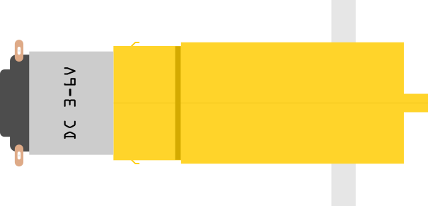
A closeup of the DC motor showing the two metal prongs.
Take a male to male jumper wire. Connect one end of the prong to the motor and the other end to the H-Bridge. Repeat this process for the other motor.
Tip
Bend the jumper wire around the prong to ensure a secure connection. Then, use electrical tape to help hold it in place! This will prevent the wire from coming loose during operation.
For advanced builders, you can cut the wire to expose its metal core, then wrap it around the prong and use electrical tape or solder to secure it in place. Be careful doing this!
Important
The two wires that connect to the motor must both plug into the same side on the H-Bridge.
Backward Motor Rotation
When you plug in the DC motors, you may notice that they rotate in the wrong direction during your tests. This is because the motors are polarized. If you plug in the motor and it rotates in the wrong direction,
Switch the wires on the H-Bridge that connect to the motor.
Switch the wires on the motor that connect to the H-Bridge.
By switching the wires, you can change the direction of the motor’s rotation. We recommend changing the wires on the H-Bridge as it is easier to access and change.
FAQs
One Motor / Wheel Not Working or Both Not Working
If one motor or wheel is not working, check the following:
Check the wiring. Make sure the wires are securely connected to the H-Bridge and motor.
Check the motor. If the motor is not working, check the wiring going to it. Try wiggling the wires and see if the motor starts spinning. This is a very common issue.
If both motors are not working, check the following:
Check the power. Make sure the batteries are connected and have power. Even if you have your Arduino plugged into your computer, the batteries must be connected.
Check the wiring. Make sure the wires are securely connected to the H-Bridge and motors.
If all else fails, ask for help. The Foundations TAs are here to help you troubleshoot and get your robot working.
Can I Use a 3D Printer or Other Chassis Type?
As fun as that would be, the assignment is locked regarding the chassis type. You can use paper or cardboard to build your chassis, but you cannot use a 3D printer or other materials.
Additional Resources
For additional resources on building the Origami Bot, refer to the following:
The Origami Bot Instructions PDF on Canvas.
Dr. Freidkes’s Building the Origami Robot YouTube video.
Dr. Schlaf’s video demonstrating how to use the h-bridge motor controller, you may start watching from
15.59" - end.The Origami Bot Code below.
The H-Bridge Control Example in this resource hub for more information on controlling DC motors with an H-Bridge.
Origami Bot Code
An updated version of the Origami Bot code is provided below. This has been expanded to include additional comments about what the code is doing, as well as align with this resource hub’s standards.
Upload the code to your Arduino, and then test your robot using its power supply to check if it is working correctly. You do not need to keep the Arduino plugged into your computer to test the robot.
/**
 * ----------------------------------------------------------------
 * Arduino Origami Bot
 * Created by Daniel Jordan, USF Department of Engineering
 * Updated by Trevor Flahardy, USF Department of Medical Engineering
 * Built Using Arduino IDE 1.8.19, updated using Arduino IDE 2.3.4
 * Tested on Feb. 4 2024
 * ----------------------------------------------------------------
 */

// Define the pins for the H-Bridge. Each pin corresponds
// to that pin on the H-Bridge. So, for example, IN1 is a connection
// from the pin labeled IN1 on the H-Bridge to the Arduino pin 4.

const int IN1 = 4; // connect IN1 on the H-Bridge to Arduino pin 4
const int IN2 = 5; // connect IN2 on the H-Bridge to Arduino pin 5

const int IN3 = 9;  // connect IN3 on the H-Bridge to Arduino pin 9
const int IN4 = 10; // connect IN4 on the H-Bridge to Arduino pin 10

/**
 * The setup function of the program. Sets all the pins as outputs
 * (ie, the Arduino is sending information to the H-Bridge).
 */
void setup()
{
    pinMode(IN1, OUTPUT);
    pinMode(IN2, OUTPUT);
    pinMode(IN3, OUTPUT);
    pinMode(IN4, OUTPUT);
}

/**
 * The loop function of the program. This is the main part of the program
 * that will run over and over again. It moves the robot forward, turns it,
 * moves it backwards, and stops it.
 */
void loop()
{
    // Moves the robot straight for 1.5 seconds
    digitalWrite(IN1, HIGH);
    digitalWrite(IN2, LOW);

    digitalWrite(IN3, HIGH);
    digitalWrite(IN4, LOW);
    delay(1500);

    // Turns the robot for 1.0 seconds
    digitalWrite(IN1, HIGH);
    digitalWrite(IN2, LOW);
    digitalWrite(IN3, LOW);
    digitalWrite(IN4, HIGH);
    delay(1000);

    // Moves the robot backwards for 1.0 seconds
    digitalWrite(IN1, LOW);
    digitalWrite(IN2, HIGH);

    digitalWrite(IN3, LOW);
    digitalWrite(IN4, HIGH);
    delay(1000);

    // Stops the robot for 1.0 seconds
    digitalWrite(IN2, LOW);

    digitalWrite(IN4, LOW);
    delay(1000);
}