Preparing to Print
You now have a model – but what next? Before you can print, you need to prepare it using slicing software. This is where you turn your 3D model into instructions that the printer can understand.
What is Slicing?
Slicing is the process of turning your digital 3D model into printable instructions – layer by layer. These instructions are saved as a special file called G-code, which your printer follows line by line.
Think of it like converting a sculpture into instructions for a robot to carve it out—except instead of carving, it’s building it up, one layer at a time!
Understanding Key Slicing Concepts
Before diving into the software, let’s cover some basic slicing terms. Don’t worry if you don’t understand all of them right away; you’ll become familiar with them as you slice models and continue through this guide.
Infill
Infill is the internal pattern that fills the inside of your model. Our models cannot be hollow, can they? Of course not, so infill gives your object strength and stability. You will not see the inside of your model once it is done printing, but infill is crucial for making sure your print does not fall apart.
There are several types of infill patterns you can use, each with their own strengths and weaknesses. Let’s walk through the most common ones you’ll encounter.
Rectilinear Infill Pattern [1]

This pattern features a single diagonal line direction per layer, with alternating orientations between adjacent layers (e.g., layers 1, 3, and 5 share the same direction, while layers 2, 4, and 6 are perpendicular), forming a non-continuous grid structure.
The use of a single-direction line per layer significantly shortens the print path, greatly improving print speed and reducing filament consumption. It is suitable for scenarios where the model does not require high structural strength.
Gyroid Infill Pattern [1]
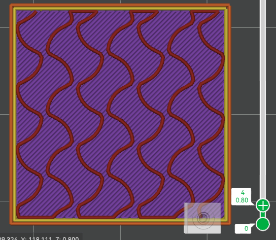
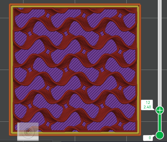

This infill pattern is a type of three-period minimal surface (TPMS) lattice structure. The spiral shape provides excellent support in all dimensions, and since there are no intersecting lines within the same layer, it offers relatively fast printing speeds.
However, due to the more complex printing path, slicing time will be longer, resulting in larger G-code files. Additionally, at higher densities and during high-speed printing, significant vibrations may occur.
At USF, you will mainly be using the Grid infill pattern, as it provides a good balance of strength and print speed. However, you can experiment with others as you become more comfortable with slicing.
But what about when your model has overhangs or bridges? These are parts of the model that extend out without support underneath, and they can be tricky to print. That’s where supports come in.
Supports
When printing models with overhangs (parts that extend out without support underneath), you may need to add supports. These are temporary structures printed alongside your model to hold up any parts that would otherwise sag or fall during printing.
Supports come in many types, but the only ones you will be using at the USF print lab are tree supports and normal supports.
Tree Supports
Tree supports sample the overhangs to identify points called “nodes.” Each node is represented as a circle. The nodes are propagated (joined) down to the build plate. During propagation, the circles may be enlarged for better strength and may be moved away from the object so the supports are less likely to collide with it [2].
When should you use tree supports over normal supports? For objects with complex structures where most of the overhangs are small, non-planar surfaces, tree supports provide a stronger support structure with less material and shorter print times, while maintaining similar surface quality [2].
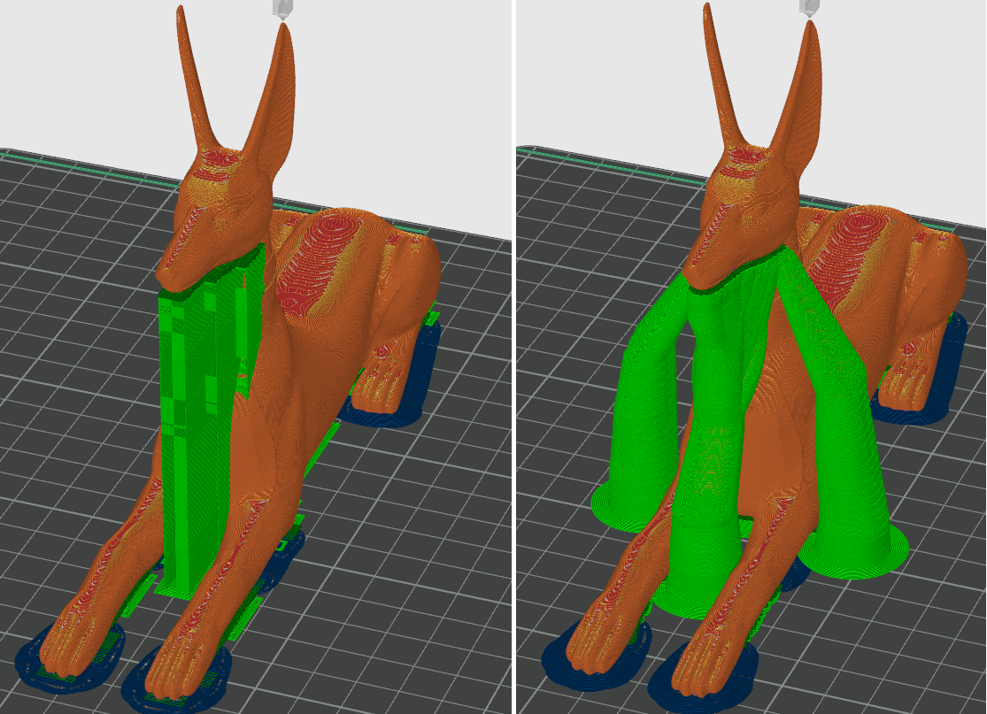
What about non-complex structures? Tree supports are still useful for large overhangs, as they provide a strong support structure with less material than normal supports. They also make it easier to remove supports after printing.
Normal Supports
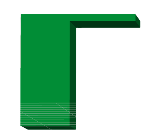
Normal supports are the traditional support structures that are printed directly under the overhangs. They can be removed after printing, but they may leave marks on the model.
When should you use normal supports over tree supports? For large planar overhangs, normal supports usually give better surface quality than tree supports.
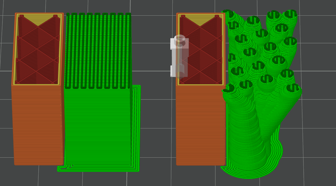
Key Differences
Now that we have covered both types of supports, which one should you use? It depends on your model’s geometry and the specific overhangs you need to support.
Tree Supports: - Best for complex structures with small, non-planar overhangs.
Stronger support with less material.
Less time cost.
Easier to remove.
Normal Supports: - Best for large planar overhangs.
Better surface quality.
May leave marks on the model.
More material used.
As you gain experience, you will develop a feel for which type works best in different situations. Always feel free to reach out for help if you are unsure.
Layer Height
Layer height refers to the vertical thickness of each deposited layer of molten material (measured in millimeters), and it is one of the most critical parameters influencing both print quality and print speed.
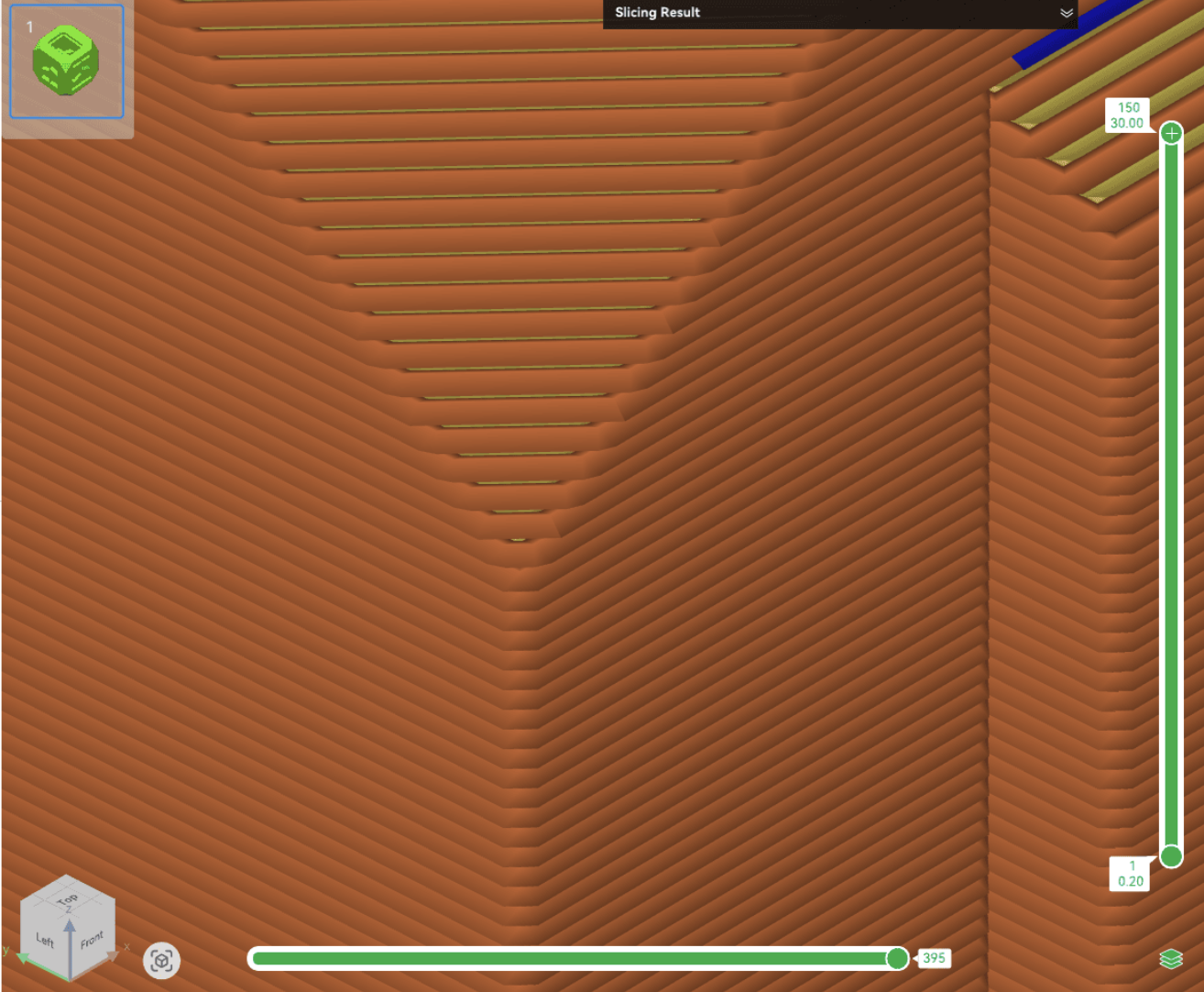
For example, with a 0.4 mm nozzle:
A smaller layer height (e.g., 0.12 mm) results in finer layering, producing smoother surfaces and better detail, but significantly increases print time.
A larger layer height (e.g., 0.28 mm) allows for faster print speeds, but may lead to visible layer lines and loss of detail.
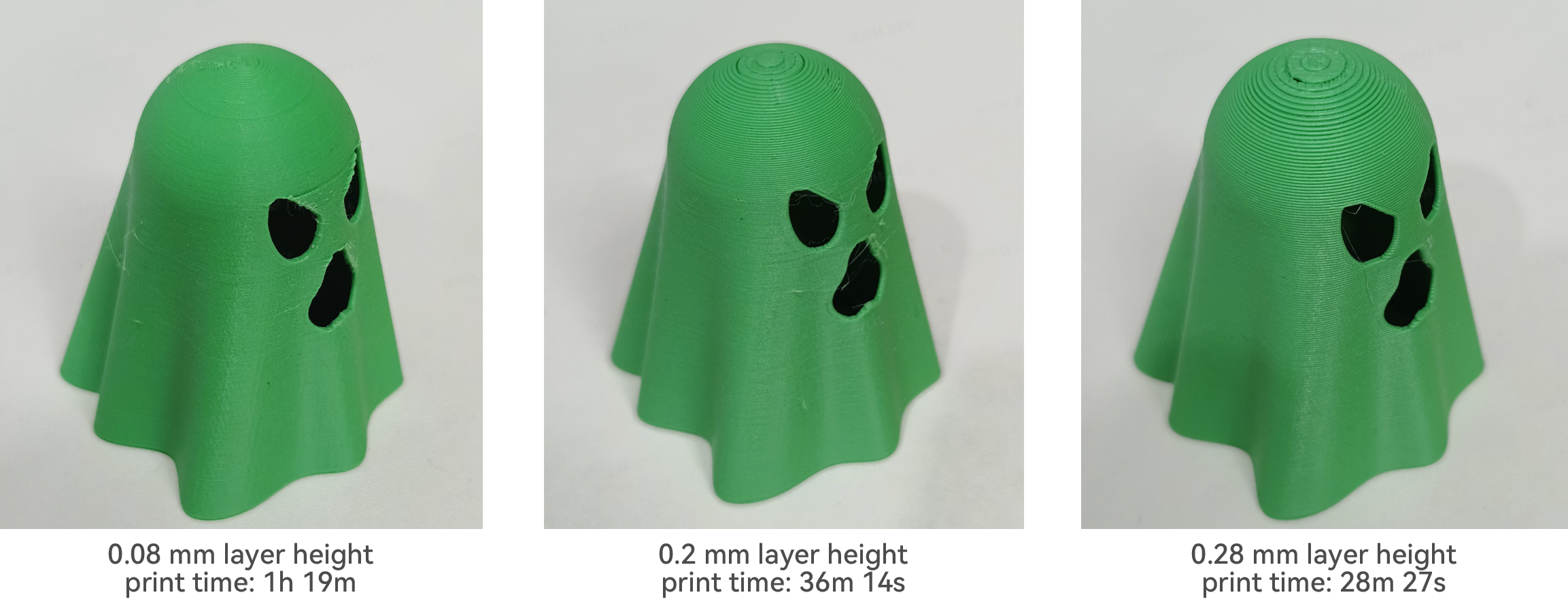
Recommended settings for layer height:
Standard Quality: 0.2 mm
High Quality: 0.12 mm
Draft Quality: 0.28 mm
Wall Count
This parameter defines the number of outer shell layers, which directly affects both the strength and surface quality of the printed model. It is generally recommended to set it between 2 and 4 layers, depending on your specific needs.
As shown in the image below, the wall structure typically includes:
Orange: Outer walls
Yellow: Inner walls
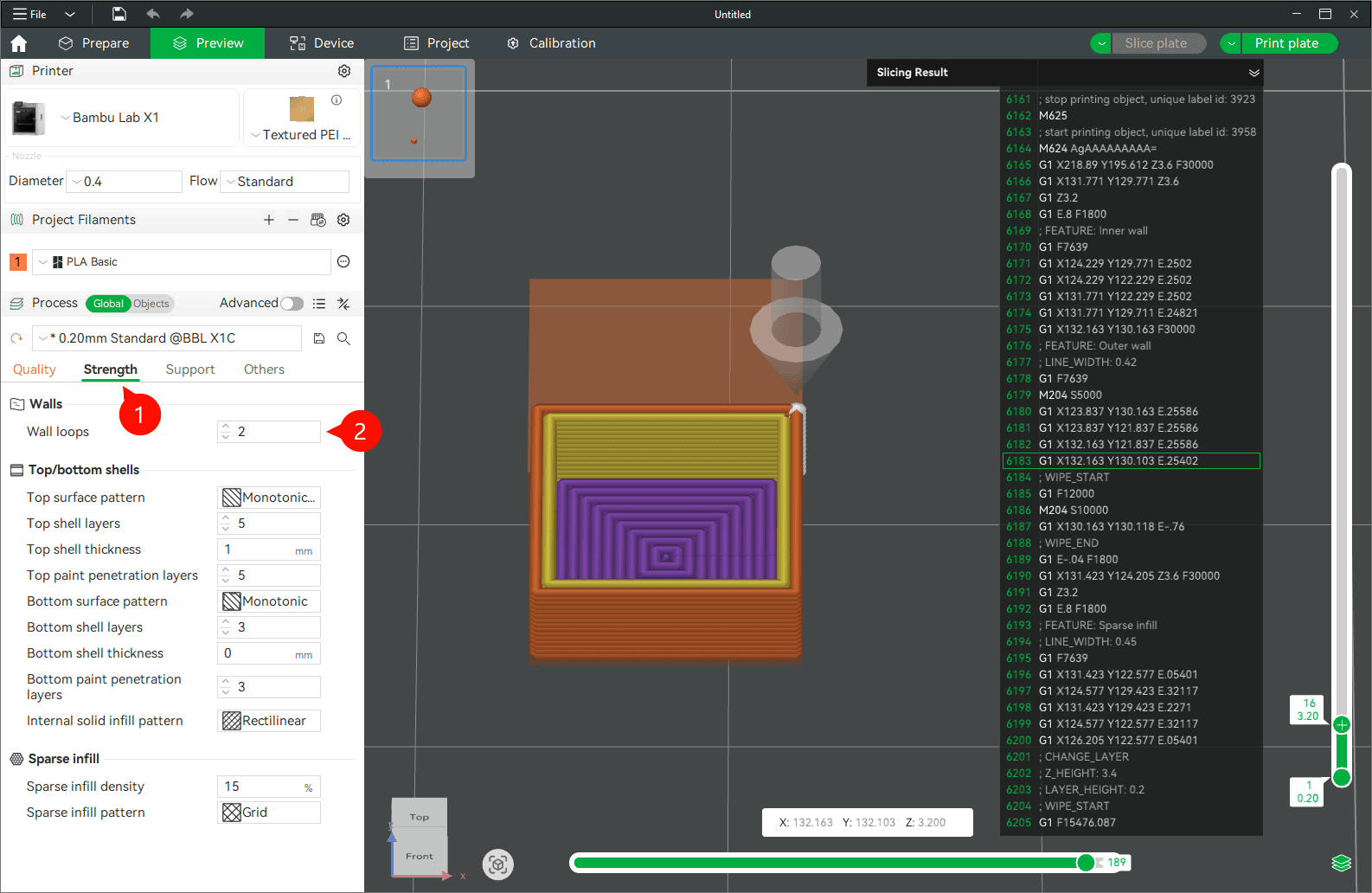
Recommended Settings:
Functional parts: Set to 3-4 walls to enhance structural strength and durability.
Decorative models: 2 walls are sufficient to save material and improve print efficiency.
Brim/Raft
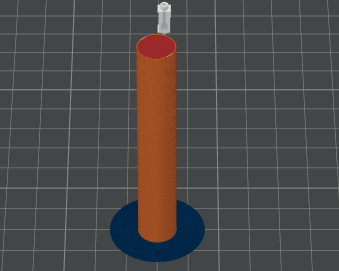
A brim is a single-layer flat area around the base of your model. Its purpose is to keep the edges of your print down and make the contact area between your print and the build plate bigger.
The bigger surface area allows your print to stick better on the build plate. This is pretty useful for tall and thin objects.
Brim can also help improve the bonding of the edges on the bottom of the model. Having a brim of sufficient width will keep the model edges in place, preventing this warping.
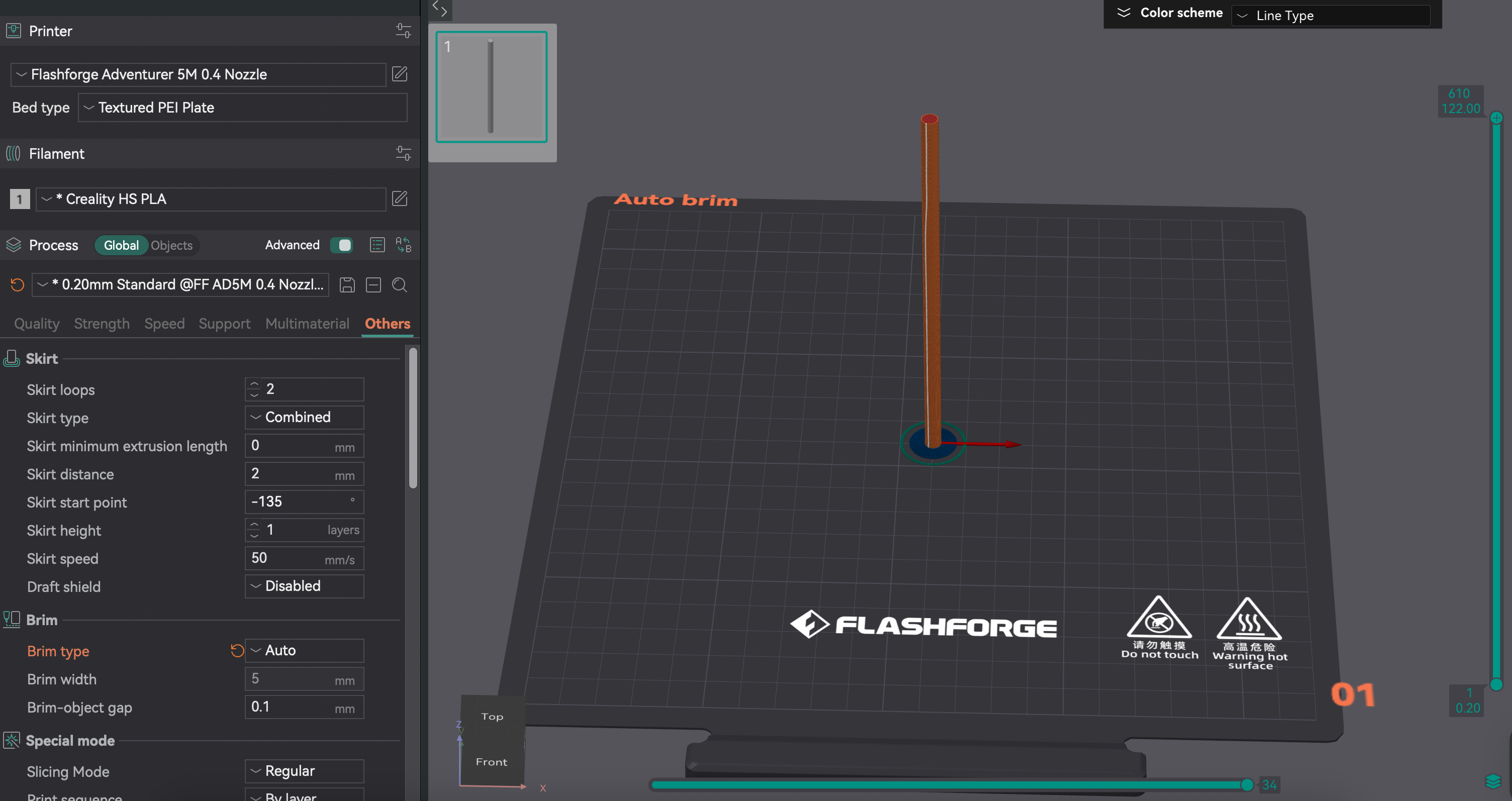
As discussed in Bed Adhesion, a brim is a great way to improve bed adhesion, especially for models with small contact areas. In Orca Flashforge, you can enable a brim in the slicing settings.
It is recommended to set the brim to auto for most prints, as it will automatically adjust the brim width based on the model’s size and shape.
Getting Started with Orca Flashforge
Now that you know about slicing, it is time to get your slicing software ready to go. Orca Flashforge is a customized version of OrcaSlicer, built specifically for the FlashForge Adventurer 5M series that you will be using in the lab.
Installing Orca Flashforge
Download Orca Flashforge
Head to the Flashforge Downloads Page and grab the latest installer for your operating system (Windows 10+ or macOS 10.15+).
Run the Installer
Follow the on-screen prompts. The setup is simple and shouldn’t take more than a minute or two.
Launch the App
Open Orca Flashforge, and the setup wizard will guide you through initial configuration.
Setup Wizard Walkthrough
The first time you launch Orca Flashforge, you’ll see a few friendly setup prompts:
Login Region – Simply pick your region (“North America”).
Select Printer – Choose the printer model you will be using:
Adventurer 5M.Select Nozzle Size – Pick the nozzle size available in the lab:
0.4mm.Select Filaments – Choose the filament you will be printing with:
PLA.
That’s it! You’re now ready to load models and start slicing.
Important
Although Orca Flashforge can wirelessly connect to 3D printers, at USF, you’ll export G-code to a USB drive and physically plug it into the printer. Easy and reliable!
Slicing and Exporting with Orca Flashforge
Now that you have Orca Flashforge set up, let’s walk through the complete workflow from loading your first model to getting G-code ready for the printer.
Loading Models
The first step in any print job is getting your 3D model into the slicer. Orca Flashforge makes this process straightforward.
Importing Your Model
To load a model, you can:
Drag and drop your STL, OBJ, or 3MF file directly into the workspace
Click the Add button in the toolbar and browse for your file
Use Ctrl+I (or Cmd+I on Mac) to open the import dialog
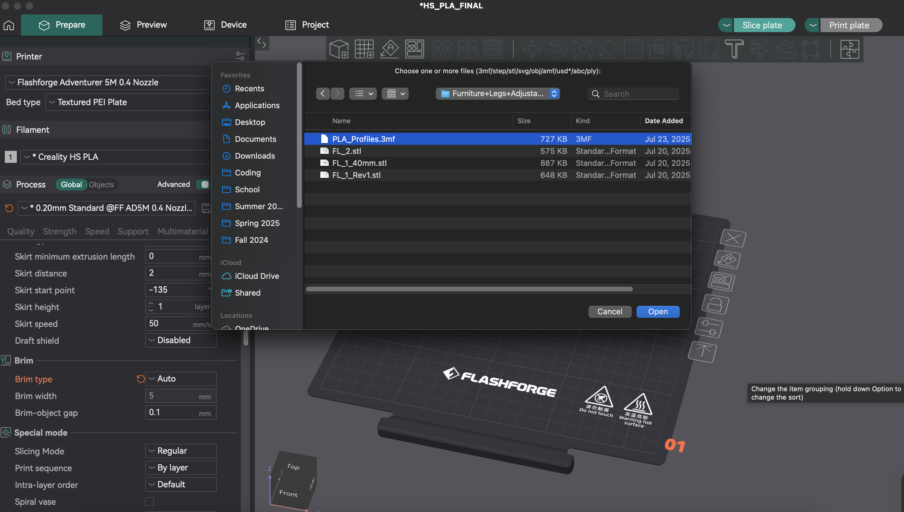
Once imported, your model will appear on the virtual build plate, ready for positioning and orientation.
Note
Importing a .3mf file into the slicer is not the same as exporting a sliced .3mf for submission. When you import a .3mf, you are loading a model or project. When you export a sliced .3mf (see Exporting a Sliced .3mf for Jotform Submission), you are saving a file that contains your slicing data for the Jotform submission system.
Orientation
How your part is positioned on the build plate is called its orientation. A thoughtful orientation can save you time and plastic, while also giving the part extra strength.
Auto Orient and Arrange
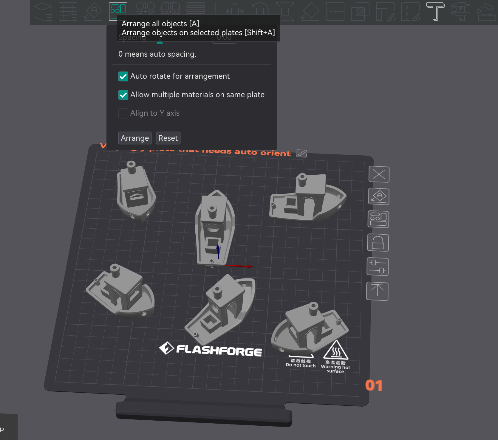
Modern 3D printing slicers are fantastic at automatically orienting parts for optimal printing. To let Orca Flashforge orient and arrange your parts for you:
First, click the Auto Orient button in the toolbar. This will analyze each part and find the best orientation for printing.
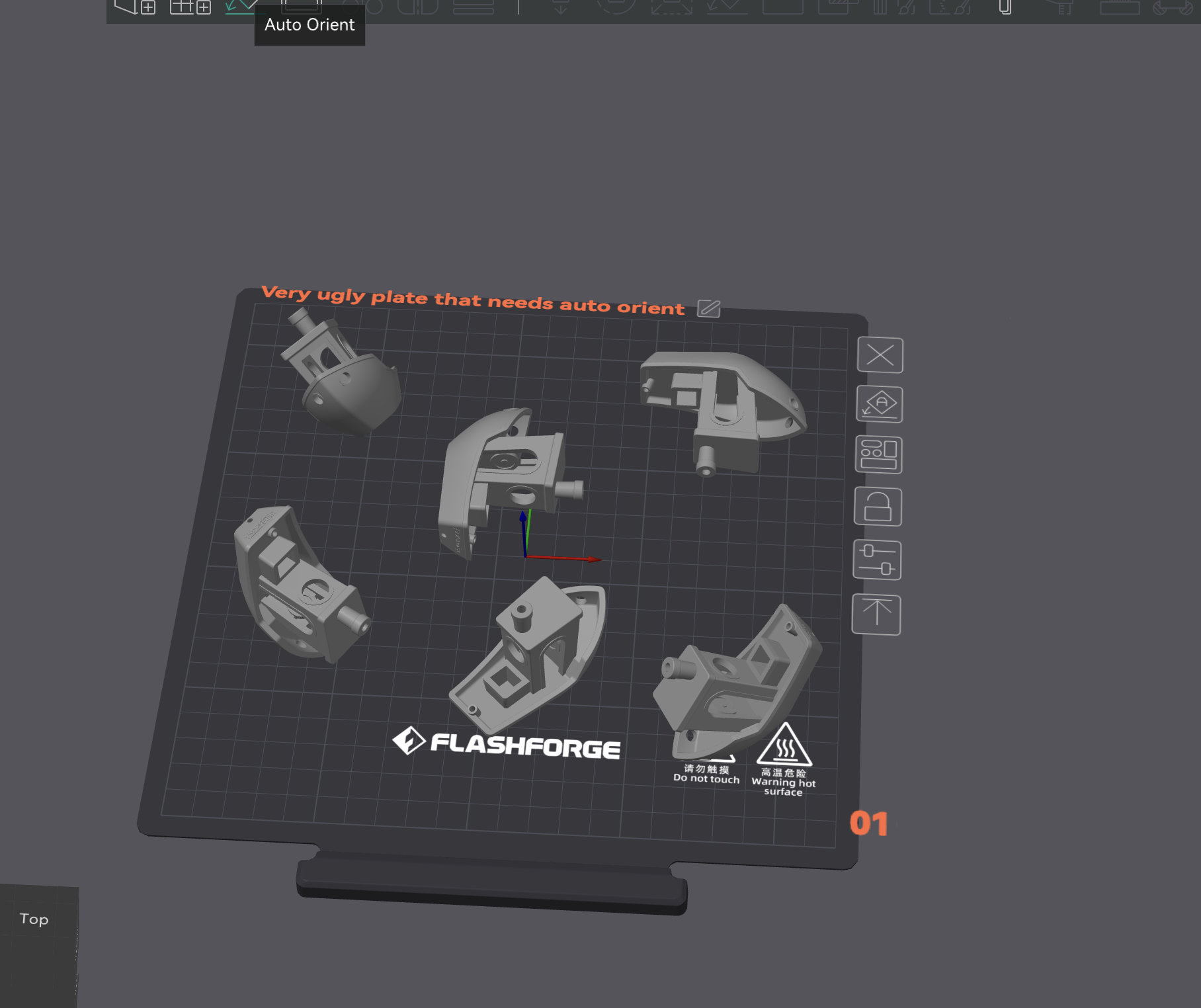
The result of this is that each part is rotated to its optimal orientation, which can save you time and material.
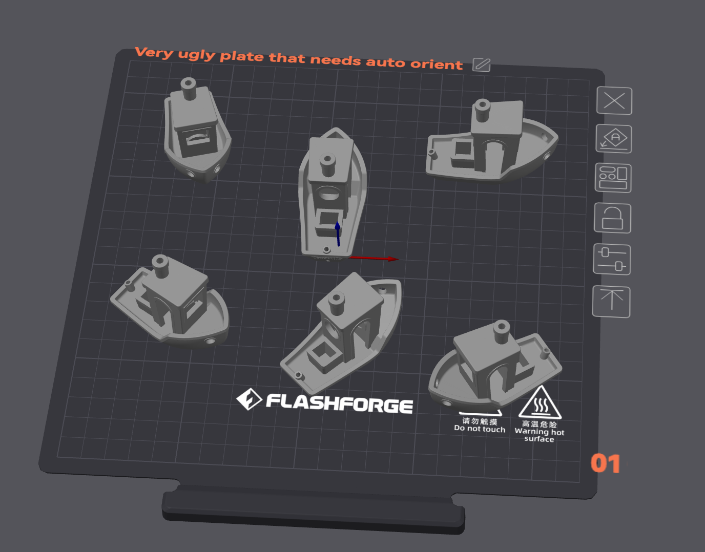
Next, click the Arrange All Objects button (or press A). This will automatically position all parts on the plate, ensuring they fit within the build area and are spaced appropriately.
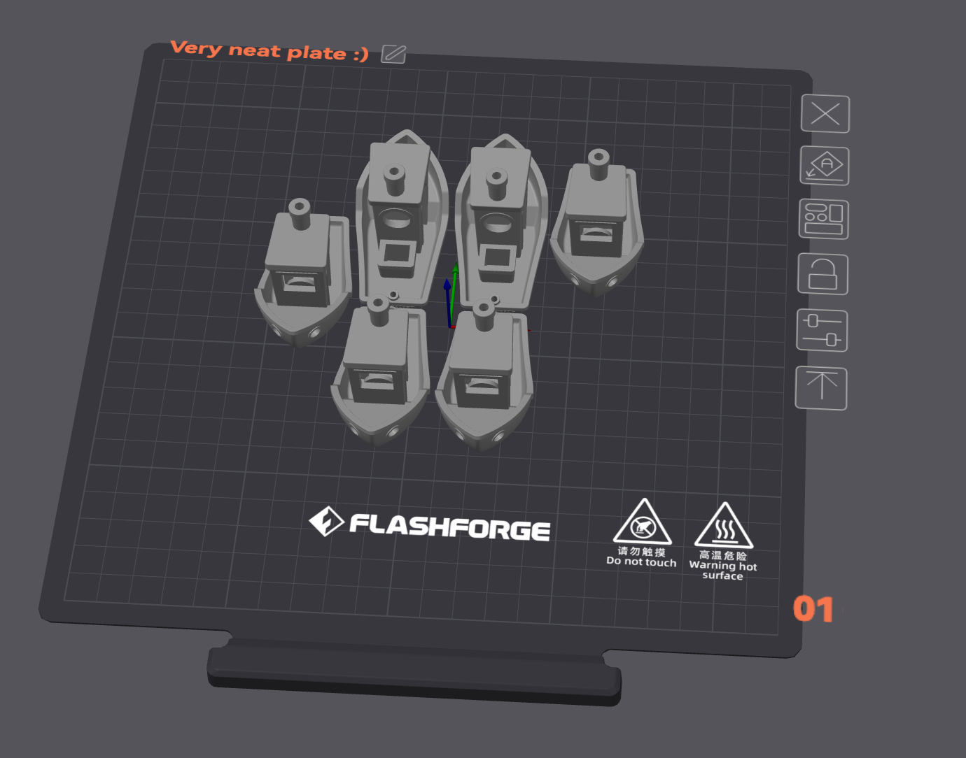
And voilà! Your parts are now optimally oriented and arranged for printing. You can still manually adjust their positions if needed, but this feature saves a lot of time and effort.
Tip
It is recommended to use the auto orient and arrange features whenever possible, as they can significantly improve print quality and reduce the need for supports with minimal effort.
Most commonly, you will not need to manually adjust the orientation of your parts, as Orca Flashforge does a great job of finding the best orientation for you.
Plate Management
In Orca Flashforge, the plate represents the printer’s build area. You can set up several plates inside a single project, and each one acts like its own print job.
Use additional plates when:
Preparing multiple parts that will not fit on the build plate all at once.
Sorting versions of a model that require different settings or filament colors.
Planning a larger project so it’s ready to print plate by plate.
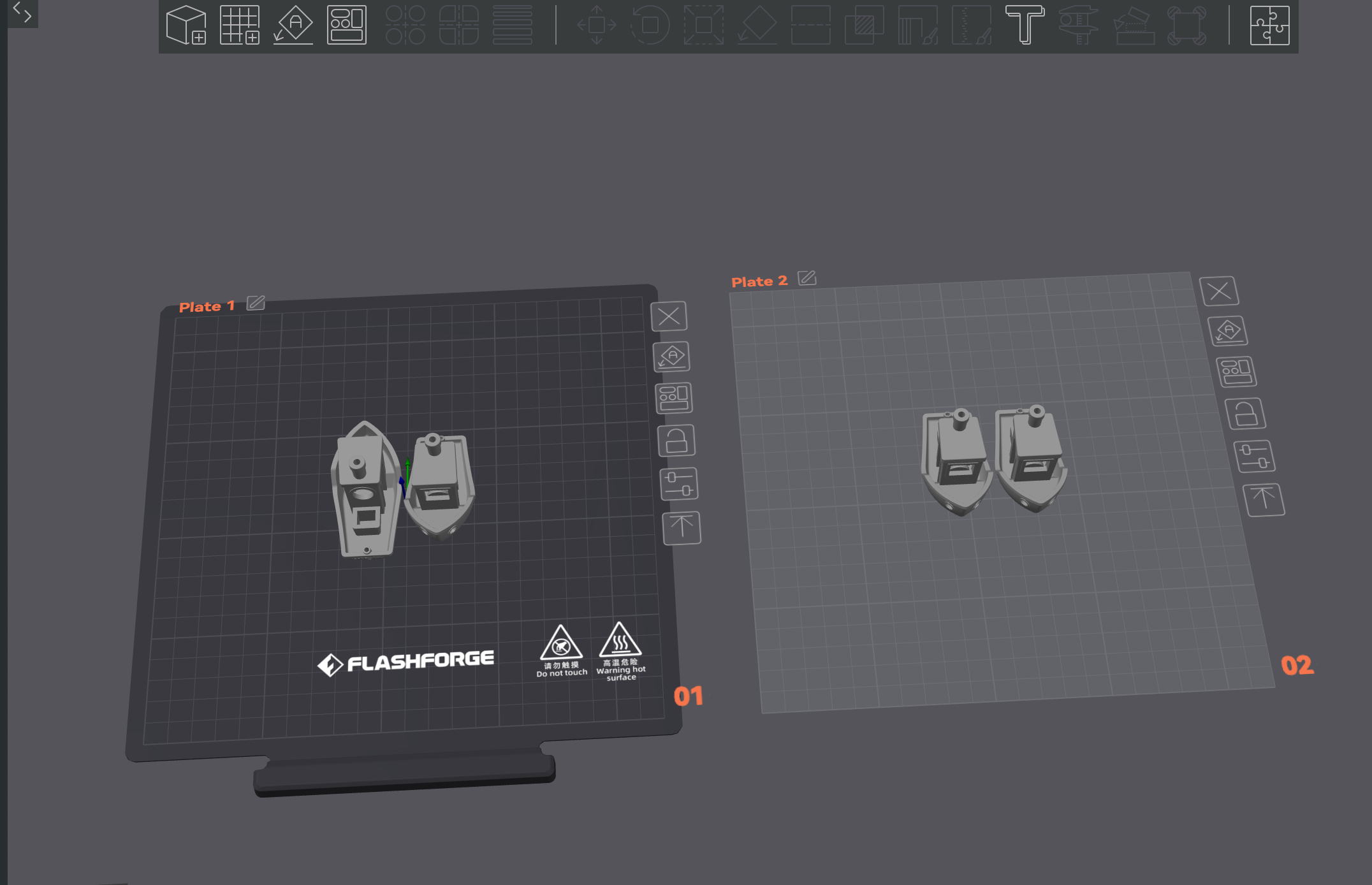
To add another plate, click the + icon on the top left of the workspace. This opens a new plate with the same settings as your current one, ready for you to load more models.
When auto orienting and arranging models, the slicer will sometimes create multiple plates automatically. This happens when your models cannot fit on a single plate due to size or orientation constraints.
Slicing Settings
With your model loaded and positioned, it’s time to configure the slicing settings. Orca Flashforge provides intelligent defaults, but understanding the key parameters helps you optimize for your specific needs.
To start, download the USF default profile here.
Important
Always use this 3MF file as your starting point. It contains all the settings you need. All you need to do is load your model into this file, orient and arrange it, and then slice. This ensures you are using the correct settings for the lab printers and that your print jobs will be accepted by the submission system.
Confirming Slicing Settings
Your default print profile should already be set for the USF defaults. The main slicing parameters are located in the left panel of the interface:
Printer Settings – Machine-specific parameters (already set for Adventurer 5M)
Filament Settings – Temperature and material properties.
Print Settings – Controls layer height, infill, and supports. This is where you will spend most of your time.
To confirm you are using the USF default profile, view all the altered settings below. An orange highlight indicates a setting that has been changed from the default. Ensure your settings match the recommended values:
Important
You may need to check the “Advanced” option in the top right corner of the settings panel to see all the tabs, and parameters, listed below!
On the Speed tab:

On the Speed tab:

On the Speed tab:

On the Support tab:

On the Others tab:

Reorient and Re-Arrange your build plates after changing any settings.
Preview Before Slicing
Before generating G-code, use the Preview feature to check your settings:
Click the Slice Plate button to generate a preview
Use the layer slider to inspect different heights of your print
Look for potential issues like insufficient supports or poor surface contact
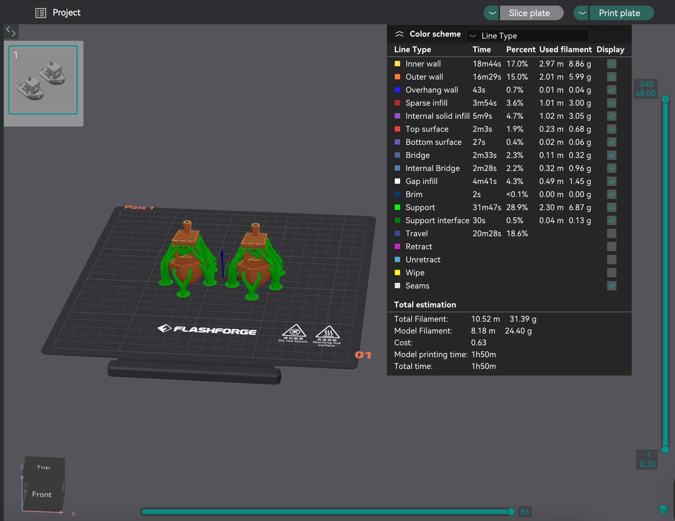
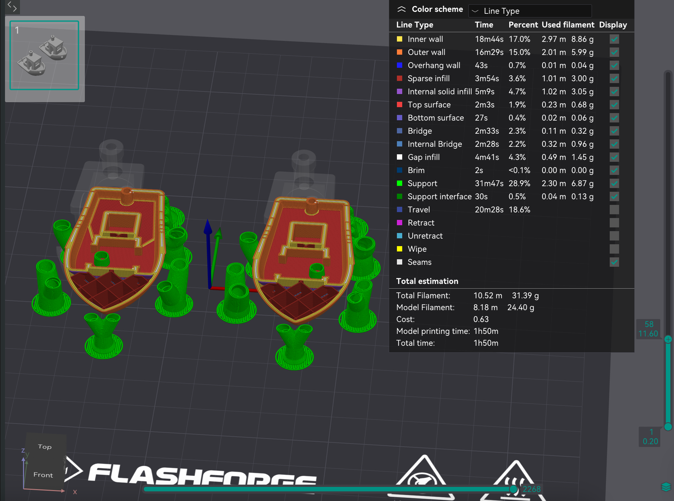
The preview shows you exactly how the printer will build your model, layer by layer.
Exporting G-Code to USB
Once you’re satisfied with your slicing settings and preview, it’s time to export the G-code file that the printer will use.
Generating G-Code
Final Slice: Click the Slice Plate button if you haven’t already. This processes your model with all current settings.
Review Print Time: Orca Flashforge will display estimated print time and material usage. This helps you plan your lab time.

Export to File: Select the dropdown next to the Print plate button (in the top right corner) and choose Export G-code file.
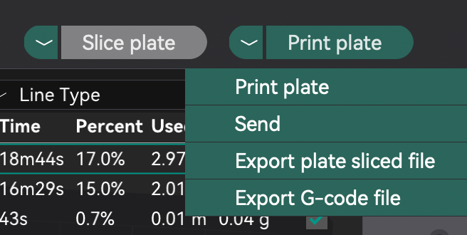
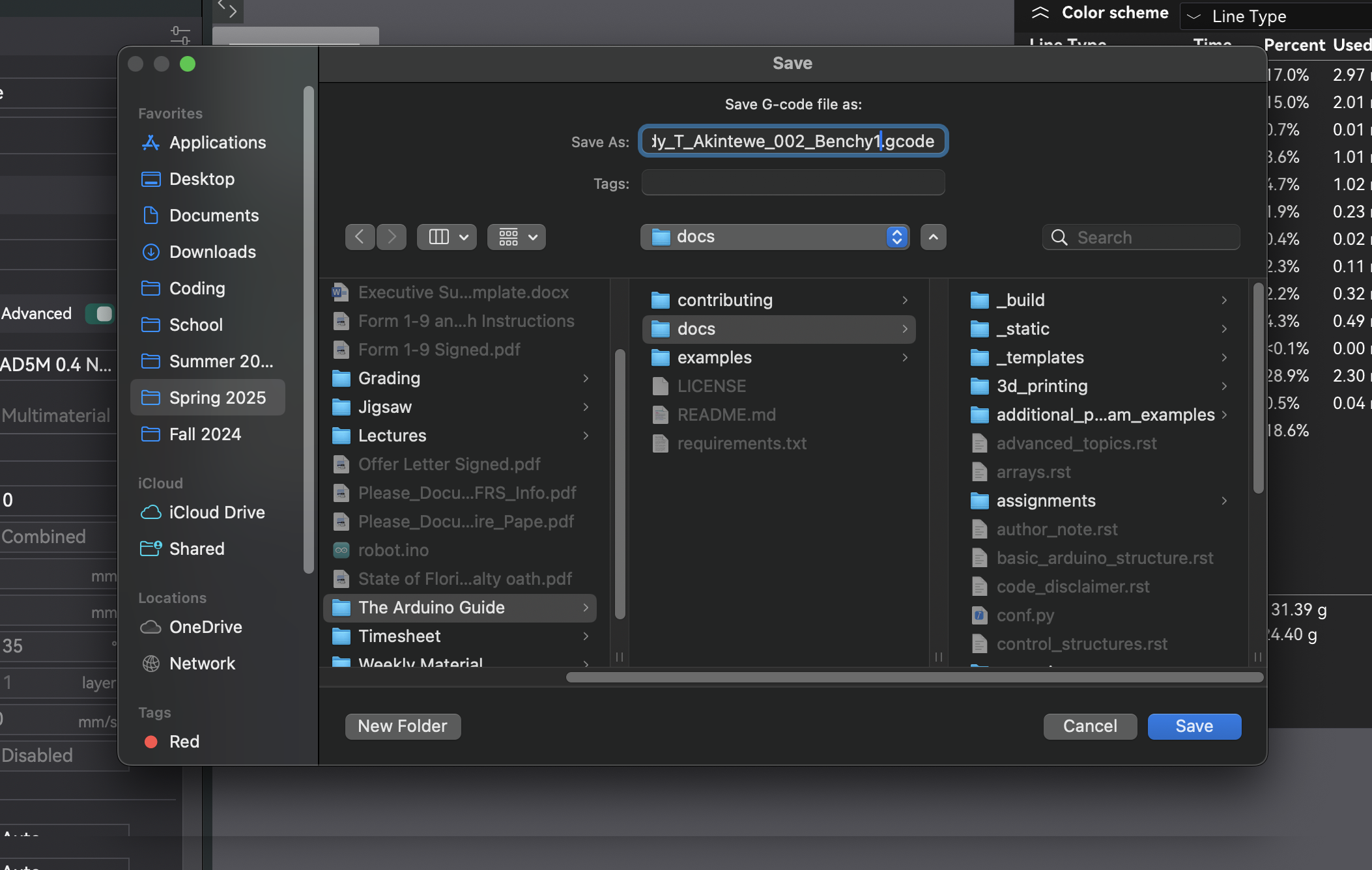
Choose Location: Save the .gcode file to your USB drive. The file name should follow this format:
LastName_FirstInitial_Professor_Section_ModelName.gcode
This helps keep your files organized and easily identifiable, and allows the TAs to quickly find your print job. If you do not follow this format, your print job will be cancelled by staff.
Note
This export is only for one plate at a time. If you have multiple plates, you will need to export each one separately.
Once your file is exported, you’re ready to move to the printer. See Responsible 3D Printing for on-printer steps and lab etiquette.
Exporting a Sliced .3mf for Jotform Submission
In addition to exporting G-code for the printer, you must also submit a sliced .3mf file through the Jotform submission system. This file contains embedded print time, filament usage, and validation data that the submission system uses to verify your print job.
Warning
A regular project save (File > Save or File > Save As) produces a .3mf file that does NOT contain slicing data. This file will be automatically rejected by the submission system. You must use the “Export plate sliced file” option described below.
How to export a sliced .3mf file:
Slice your model: Click the Slice Plate button to slice your model with all current settings. Wait for slicing to complete.
Open the export dropdown: After slicing completes, locate the export/print button (in the top right corner). Click the dropdown arrow next to this button — do not click the main button itself.
Select “Export plate sliced file”: From the dropdown menu, choose “Export plate sliced file”. This is the only option that produces a .3mf with the required embedded data.
Save the file: Save the resulting .3mf file to your computer. This is the file you must upload to the Jotform submission.
Important
This applies to Orca Flashforge. The key distinction is:
File > Save / Save As = project file only (no slicing data) — will be rejected
Export plate sliced file (from the dropdown) = sliced file with print time, filament usage, and validation data — this is what you must submit
If you are unsure whether your file is correct, check the file size: a sliced .3mf will typically be significantly larger than an unsliced project save because it contains the full slicing data.
Note
Like G-code export, this export is only for one plate at a time. If you have multiple plates, you will need to export each one separately.